Frequency response is the measure of any system's output spectrum in response to an input signal. In the audible range it is usually referred to in connection with electronic amplifiers, microphones and loudspeakers. Radio spectrum frequency response can refer to measurements of coaxial cables, category cables, video switchers and wireless communications devices. Subsonic frequency response measurements can include earthquakes and electroencephalography (brain waves).
Frequency response requirements differ depending on the application. In high fidelity audio, an amplifier requires a frequency response of at least 20–20,000 Hz, with a tolerance as tight as ±0.1 dB in the mid-range frequencies around 1000 Hz, however, in telephony, a frequency response of 400–4,000 Hz, with a tolerance of ±1 dB is sufficient for intelligibility of speech
Frequency response curves are often used to indicate the accuracy of electronic components or systems. When a system or component reproduces all desired input signals with no emphasis or attenuation of a particular frequency band, the system or component is said to be "flat", or to have a flat frequency response curve.
The frequency response is typically characterized by the magnitude of the system's response, measured in decibels (dB), and the phase, measured in radians, versus frequency. The frequency response of a system can be measured by applying a test signal, for example:
1. - Applying an impulse to the system and measuring its response
2. - Sweeping a constant-amplitude pure tone through the bandwidth of interest and measuring the output level and phase shift relative to the input
3.- Applying a signal with a wide frequency spectrum (for example digitally-generated maximum length sequence noise, or analog filtered white noise equivalent, like pink noise), and calculating the impulse response by deconvolution of this input signal and the output signal of the system
These typical response measurements can be plotted in two ways: by plotting the magnitude and phase measurements to obtain a Bode plot or by plotting the imaginary part of the frequency response against the real part of the frequency response to obtain a Nyquist plot
Once a frequency response has been measured (e.g., as an impulse response), providing the system is linear and time-invariant, its characteristic can be approximated with arbitrary accuracy by a digital filter. Similarly, if a system is demonstrated to have a poor frequency response, a digital or analog filter can be applied to the signals prior to their reproduction to compensate for these deficiencies.
Frequency response measurements can be used directly to quantify system performance and design control systems. However, frequency response analysis is not suggested if the system has slow dynamics.
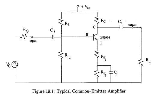
Frequency Response of Amplifiers.
The essential purpose of an amplifier is to accept an input signal and provide an enhanced copy of that signal as an output. . In addition to being classified by function, amplifiers are classified by frequency response. The
In general the frequency response of an electronic circuit.
Low Frecuency  High Frecuency
mid-band
There is a 'mid-band' range of operation for which the gain is substantially independent of frequency, bounded by 'high' and 'low' frequency ranges in which the gain is degraded. An amplifier is 'wide-band' if the ratio of a frequency measuring the onset of the high-frequency degradation to a corresponding frequency for low frequency degradation is relatively large. A basic audio amplifier, for example, has a substantially 'flat' response extending from about 100 Hz to roughly 10KHz. 'Narrow-band' amplifiers, used for more specialized purposes, approximate selective amplification at a single frequency.
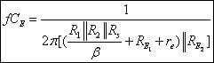
To simplify consideration of the frequency response of wide-band amplifiers analysis generally is separated into three frequency ranges. The argument used to justify this separation is that those circuit components associated with low-frequency degradation have by definition lost significant influence on the response in mid-band, and supposing a monotonic behavior have no influence on the high-frequency response. The converse argument removes the influence at low frequencies of those components affecting the high frequency response. And, of course, in mid-band by definition neither of these sets of components influences the response significantly. The mid-band range is the one assumed in previous work, for example by neglecting the influence of coupling and bypass capacitors.
Fuente de origen: wps.prenhall.com/...7/0,9426,1508470-,00.html
Datos personales: Lenny. Z Perez M.
Asignatura: EES
Connect to the next generation of MSN Messenger Get it now!